|
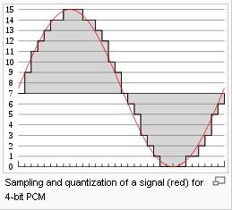
这是JRTPLIB@Conference系 列的第五部《PCM 和G.711编码相关》,本系列的主要工作是实现一个基于JRTPLIB的,建立在RTP组播基础上的多媒体视频会议系统。这只是一个实验系统,用于学习 JRTPLIB、RTP、和多媒体相关的编程,不是一个完善的软件工程。而且,我只会在业余的时间出于兴趣写一写。有志同道合的朋友可以通过tinnal@136.com这个邮箱或博客回复(推荐)和我交流。 In the diagram, a sine wave (red curve) is sampled and quantized for PCM. The sine wave is sampled at regular intervals, shown as ticks on the x-axis. For each sample, one of the available values (ticks on the y-axis) is chosen by some algorithm (in this case, the floor function is used). This produces a fully discrete representation of the input signal (shaded area) that can be easily encoded as digital data for storage or manipulation. For the sine wave example at right, we can verify that the quantized values at the sampling moments are 7, 9, 11, 12, 13, 14, 14, 15, 15, 15, 14, etc. Encoding these values as binary numbers would result in the following set of nibbles: 0111, 1001, 1011, 1100, 1101, 1110, 1110, 1111, 1111, 1111, 1110, etc. These digital values could then be further processed or analyzed by a purpose-specific digital signal processor or general purpose CPU. Several Pulse Code Modulation streams could also be multiplexed into a larger aggregate data stream, generally for transmission of multiple streams over a single physical link. This technique is called time-division multiplexing, or TDM, and is widely used, notably in the modern public telephone system. There are many ways to implement a real device that performs this task. In real systems, such a device is commonly implemented on a single integrated circuit that lacks only the clock necessary for sampling, and is generally referred to as an ADC (Analog-to-Digital converter). These devices will produce on their output a binary representation of the input whenever they are triggered by a clock signal, which would then be read by a processor of some sort.
To produce output from the sampled data, the procedure of modulation is applied in reverse. After each sampling period has passed, the next value is read and the output of the system is shifted instantaneously (in an idealized system) to the new value. As a result of these instantaneous transitions, the discrete signal will have a significant amount of inherent high frequency energy, mostly harmonics of the sampling frequency (see square wave). To smooth out the signal and remove these undesirable harmonics, the signal would be passed through analog filters that suppress artifacts outside the expected frequency range (i.e., greater than , the maximum resolvable frequency). Some systems use digital filtering to remove the lowest and largest harmonics. In some systems, no explicit filtering is done at all; as it's impossible for any system to reproduce a signal with infinite bandwidth, inherent losses in the system compensate for the artifacts — or the system simply does not require much precision. The sampling theorem suggests that practical PCM devices, provided a sampling frequency that is sufficiently greater than that of the input signal, can operate without introducing significant distortions within their designed frequency bands. The electronics involved in producing an accurate analog signal from the discrete data are similar to those used for generating the digital signal. These devices are DACs (digital-to-analog converters), and operate similarly to ADCs. They produce on their output a voltage or current (depending on type) that represents the value presented on their inputs. This output would then generally be filtered and amplified for use. 我来总结一下吧,这里的PCM指线性PCM,说线性是为了和下面的非线性作对比 的。如果大家学习计算机组成原理,那就很好理解了,PCM其实就是音频经过ADC后的输出。但要注意,我们常用的ADC输入一般是0~5V,而对音频来说 输入是可+也可-的,这也很好理解。我们常用的PCM一般是16位的。 There are two main compression algorithms defined in the standard, the µ-law algorithm (used in North America & Japan) and A-law algorithm (used in Europe and the rest of the world). Both are logarithmic, but A-law was specifically designed to be simpler for a computer to process. The standard also defines a sequence of repeating code values which defines the power level of 0 dB. The µ-law and A-law algorithms encode 14-bit and 13-bit signed linear PCM samples (respectively) to logarithmic 8-bit samples. Thus, the G.711 encoder will create a 64 kbit/s bitstream for a signal sampled at 8 kHz. G.711, also known as Pulse Code Modulation (PCM), is a very commonly used waveform codec. G.711 uses a sampling rate of 8,000 samples per second, with the tolerance on that rate 50 parts per million (ppm). Non-uniform quantization with 8 bits is used to represent each sample, resulting in a 64 kbit/s bit rate. There are two slightly different versions; μ-law, which is used primarily in North America, and A-law, which is in use in most other countries outside North America. G.711 μ-law tends to give more resolution to higher range signals while G.711 A-law provides more quantization levels at lower signal levels. When using μ-law G.711 in networks where suppression of the all 0 character signal is required, the character signal corresponding to negative input values between decision values numbers 127 and 128 should be 00000010 and the value at the decoder output is -7519. The corresponding decoder output value number is 125.
A-law encoding thus takes a 13-bit signed linear audio sample as input and converts it to an 8 bit value as follows:
Where s is the sign bit. So for example, 1000000010101111 maps to 10001010 (according to the first row of the table), and 0000000110101111 maps to 00011010 (according to the second).
这个我们也来理解理解,无非就是说,为了只表示语音,用16位取样精度太浪费空间了,用8位就够了, 不 过直接用8位取样效果又太差,然后就有人来研究,原来人对小信号敏感一点,这样,就有人想出一个非线性的转换,能把16Bit的最大值65535转换成8 位的最大值255的,注意这是一个非线性转换,对小的信号描述的详细点,对大的信号则描述的粗略一点。这样,就可以用8位比较清楚的记录下来语音了。真聪 明! 参考网页: http://telecom.tbi.net/digpcm.htm http://en.wikipedia.org/wiki/G.711 http://www.lincoln.edu/math/rmyrick/ComputerNetworks/InetReference/127.htm http://en.wikipedia.org/wiki/G.711 (猫头上的鹰-猫头鹰) |